
A CLOSER LOOK AT INTERMITTENT BONDED RIBBON TECHNOLOGY

Intermittent Bonded Ribbon Production Line Available For Sale

With a listed operating speed of 600 m/min, this machinery offers substantial capacity for optical-fiber production. Before making purchasing plans, buyers should verify the actual speed, configuration, and operating conditions with the manufacturer.

Shanghai Weiye OFC provides a system engineered to manufacture 12- and 16-fiber rollable ribbons. The published product information covers capabilities, technical details, and supplied systems, helping U.S. buyers begin evaluating the equipment against their manufacturing needs.

Begin by examining the stated equipment configuration, then ask the supplier for pricing, installation requirements, and project-specific alternatives. Doing so can clarify which specifications and options are relevant to your facility and production objectives.

Shanghai Weiye Optic Fiber Communication Equipment Co., Ltd. provides its business address as 201 Minyi Road, Songjiang District, Shanghai. Consider the product listing a preliminary information source, and confirm up-to-date specifications and commercial terms with the supplier. A detailed quotation request can help advance your equipment evaluation.


Key Takeaways

  • The stated operating speed is 600 m/min, although the manufacturer should confirm the applicable conditions.
  • The machinery is intended to manufacture rollable ribbons containing 12 or 16 fibers.
  • Information about equipment functions, specifications, and included systems appears on the product page.
  • Request details about pricing, installation requirements, and project-specific customization.
  • The supplier provides a business address in Songjiang District, Shanghai.

Intermittent Bonded Ribbon Production Line Overview

The manufacturer identifies this machinery as suitable for 12- and 16-fiber rollable IBR formats. Its product page specifies a construction speed of 600 m/min and a fiber diameter of Ф245 μm ±10 μm. Because these figures represent stated machine specifications, buyers should verify achievable speeds and operating conditions with the manufacturer.
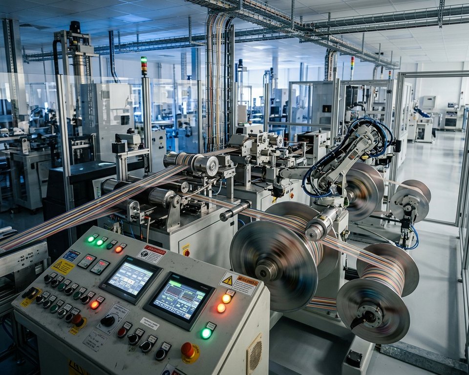
Intermittent Bonded Ribbon Production LineIntermittent Bonded Ribbon Production Line

Designed To Produce Twelve- And Sixteen-Fiber Rollable Ribbons

Two fiber-count options are supported by the configuration for manufacturing rollable ribbons. Buyers can use these options as a starting point for checking compatibility with target formats, fiber sizes, and handling requirements.

How Intermittent Bonding Supports Flexible Fiber Arrangement

The patent’s design examples describe neighboring fiber subunits joined by adhesive bonds positioned at intervals. One illustrated spacing range extends from 10 mm to 1,000 mm. This differs from a continuously bonded structure in which the connection extends across the full ribbon length.

By spacing the bonds apart, the assembly can move between a mostly planar arrangement and a rolled, curled, or folded shape. These bond-spacing figures describe examples of the design approach and should not be interpreted as stated equipment settings.

  • Machine details: 12 or 16 fibers, a stated speed of 600 m/min, and a diameter of Ф245 μm ±10 μm.
  • Patent example: Illustrative spacing between adhesive bonds of 10 mm to 1,000 mm.
  • Design benefit: Adaptable handling when the ribbon takes different shapes.

Uses In Optical Fiber Cable Manufacturing

Adjustable fiber layouts may allow cable designers to combine convenient splice access with space-efficient packaging. The patented design keeps fibers arranged in order while permitting sections between bonded points to shift as the cable is assembled.

High Fiber Density And Compact Cable Designs

For mass fusion splicing, an optical fiber ribbon can be arranged flat before being folded or rolled into a more compact cable. Potential advantages described in the patent include smaller cable constructions and an increased ratio of fiber area to overall cable cross-sectional area. Actual performance and dimensions will vary according to the overall cable design and the application for which it is intended.

Organizing Fiber Ribbons To Support Efficient Fusion Splicing

This design supports orderly fiber handling during splicing while providing flexibility for subunit movement in the assembly process. The manufacturer’s material-handling specifications identify payoff reel capacities of 25.2 km and 50.4 km of fiber. These reel capacities can be compared with the facility’s cable-manufacturing needs and material-handling setup.

Design characteristic Potential use Consideration for buyers
Planar fiber arrangement Fusion splicing of multiple fibers Verify the needs of your splicing process
Ribbon configuration that folds or rolls Space-efficient cable packaging Review the overall cable construction
25.2 km and 50.4 km capacity payoff reels Planning material-handling operations Match the reel capacity to production operations

Production Line Specifications And Performance

Compare the equipment’s published performance figures with your manufacturing requirements before requesting a quotation. Reel compatibility and facility utility requirements are also important considerations for installation planning.

Production Speed, Fiber Diameter, And Attenuation

The stated construction speed is 600 m/min. The specified fiber diameter is Ф245 μm ±10 μm, while additional attenuation is stated as ≤0.01 dB/km at 1550 nm. Confirm the measurement conditions and expected performance directly with the manufacturer.

Payoff And Take-Up Reel Compatibility

Two payoff reel sizes are offered, with each full reel limited to 10 kg. For take-up, the equipment accepts either a T-type reel or a fiber-optic reel. Check whether the preferred reel format suits your existing handling equipment and procedures.

Site Utilities And Environment

Plan for a 380 V ±10% power connection using a three-phase, five-wire system. Its specified operating environment is enclosed, clean, dry, and protected from drafts, with temperatures of 15 to 25°C and relative humidity no higher than 85%. Nitrogen must be supplied at 7 bar with 99.99% purity, together with compressed air at 6 bar. Check all utility connections in advance of installing the equipment.

Specification Listed requirement Installation planning note
Payoff reels Ф236 × Ф25.4 × 108 mm; Ф267 × Ф25.4 × 180 mm; maximum full-reel weight ≤10 kg Verify reel dimensions and weight
Reel used for take-up T-type reel: Φ410 × Φ50.8 × 391 mm, alternatively a fiber-optic reel Verify the preferred reel format
Electrical and environmental requirements 380 V ±10%; 15 to 25°C; relative humidity ≤85% Provide a clean, dry area without drafts
Gas supply Nitrogen: 7 bar, 99.99% purity; air: 6 bar Check available gas capacity before equipment setup

Equipment For Fiber Payoff And Gathering

The payoff and gathering assemblies direct optical fibers into the ribbon-forming area. Their control systems support consistent feeding and help protect individual fibers throughout handling.

Tension-Controlled Payoff System For Sixteen Spools

The payoff assembly holds 16 spools and provides traversing along with separately adjustable tension settings. The permitted weight for an individual spool is up to 10 kg. Detailed specifications indicate a tension range of 0.4 to 2 N, accuracy of ±0.02 N, and a 550 W motor. Another overview gives a range of 40 to 150 g and accuracy of ±2 g, so buyers should confirm which specification applies to their configuration.

Fiber Guidance, Break Detection, And Static Control

U-groove guides, multi-groove gathering rollers, and anti-jump components channel fibers into the forming section. A break-detection system and alarms notify operators when problems occur. Safe handling is supported by protective guards and a pneumatic clamping mechanism. A rod-type electrostatic dust collector is positioned at the fiber exit, and additional anti-static devices help control dust throughout the gathering path.

Component Specified details Intended function
Payoff Capacity for 16 spools, each weighing up to 10 kg Feeds optical fibers with traversing movement
Motor and tension system 0.4 to 2 N with ±0.02 N accuracy; 550 W Maintains controlled fiber payoff
Guidance and safety Grooved rollers, alarms, guards, and pneumatic clamping Directs fibers and supports safe handling
Static control Rod-style electrostatic collector with anti-static devices Helps reduce dust near fiber routes

Intermittent Adhesive Dispensing And Precision Molding

The ribbon-forming platform allows operators to control the mold position and placement of adhesive. These settings allow the production process to be adapted to the intended ribbon configuration.

Ribbon Formation Using An Adjustable IBR Mold Platform

Ribbon formation uses three mold assemblies, each capable of holding up to five Nordson EFD jet valves. Operators can position the mold within 0 to 15 mm and adjust its base temperature from 20°C to 60°C. Grouped precision dispensing valves are installed on slide tables so operators can refine their alignment and place adhesive dots carefully.

Adjustable Nozzle Configurations For Twelve- And Sixteen-Fiber Ribbon Production

The 12-fiber configuration employs a 5+5+1 valve arrangement. Production of the 16-fiber format uses a 5+5+5 configuration. The control interface enables changes to dot count and spacing according to the ribbon configuration being manufactured. A dedicated adhesive is required for the coating and curing stages.

Process setting 12-Fiber Format Format With 16 Fibers
Valve arrangement Valve arrangement of 5+5+1 Valve arrangement of 5+5+5
Mold adjustment 0 to 15 mm adjustment Adjustment range of 0 to 15 mm
Temperature of the mold base 20°C to 60°C operating range 20°C to 60°C operating range

Curing Bonded Fiber Ribbons With UV-LED Technology

The curing assembly applies UV exposure in stages to harden adhesive throughout the fiber structure. Prospective buyers can assess the oven configuration and listed operating specifications to determine whether the equipment suits their production process.

Pre-Curing And Main Curing Stages

Three dedicated LED-UV ovens rated at 800 W each perform the pre-curing operation. Fibers from each mold group pass through their respective pre-curing unit before entering the principal 6 kW post-curing oven. The system uses adjustable shutters to help contain UV exposure and minimize nitrogen losses. Published specifications identify a dominant wavelength of 395 nm ±3 nm, a curing degree of at least 85%, and post-curing power of at least 2.5 kW.

Managing Nitrogen Supply And Curing Performance

The nitrogen flow rate and pressure can be adjusted by hand. Automatic functions also start nitrogen delivery during startup and stop it at shutdown. At production speed under continuous stable conditions, the specified lamp-array power consumption is no more than 80% of total power. These specifications provide a reference for comparing equipment, although testing conditions should be verified with the supplier. Discuss how the operating settings may change depending on the adhesive and materials selected.

Visual Monitoring, Capstan, And Take-Up

Visual inspection and consistent winding help preserve fiber quality as material passes through the production line. The published operating settings also offer buyers useful criteria for comparing equipment against their cable production requirements.

Real-Time Inspection Of Fiber Colors And Adhesive Dot Placement

Real-time magnified views are displayed through the machine’s microscope and camera system. The display allows operators to check the sequence of fiber colors and confirm adhesive resin dots at each dispensing position. This inspection helps identify ribbon problems before the material enters the winding stage.

Precision Take-Up With Servo-Controlled Traction

A 1 kW AC servo motor powers the capstan’s Φ190 mm traction wheel. The listed measurement accuracy exceeds 1‰. Operators can set tension between 50 and 500 g while maintaining an accuracy of ±5 g. These operating parameters help maintain careful fiber-ribbon handling as the material advances through the line.

Take-up operation is rated at 600 m/min with a spool weight limit of 30 kg. The servo-driven take-up and traversing assemblies support uniform positioning during winding. Cable pitch can be adjusted continuously between 1 and 6 mm. Position detection and direction changes are supported by a photoelectric sensor. Confirm that the operating conditions and settings are suitable for your target cable design with the supplier.

Production Monitoring And Electrical Control Systems

Accessible controls allow operators to adjust settings, check equipment status, and arrange orderly shutdowns. According to the manufacturer, the machinery incorporates Siemens controls alongside Schneider Electric switchgear.

Operating The Production Line Through PLC And Touchscreen Controls

The ribbon production line uses Siemens S7-1200 and S7-1500 PLCs with a 10.4-inch Siemens touchscreen interface. Low-voltage switchgear is supplied by Schneider Electric. Operators may control the entire line with interlocked units or run individual sections independently.

Process Settings, Warning Alarms, And Preset-Length Shutdowns

The touchscreen allows adjustment of process parameters, curing-oven activation, wire-feed settings, and alarm information. Additional displays provide lamp runtime, real-time current readings, curing-oven temperature, and total machine operating hours. The meter-counter calibration feature allows displayed counts to be aligned with the distance actually traveled.

A preset length can be entered to initiate slowing or stopping of the machine. This provides a practical way to control the end of a cable production run. Ask the manufacturer to confirm control capabilities and setup requirements before placing an order.

Control feature Published specification Use
PLC and display Siemens S7-1200/S7-1500; 10.4-inch touchscreen Configure settings and examine production data
Electrical components Schneider Electric low-voltage switchgear Supports electrical control operations
Equipment monitoring and shutdown control Operating data for lamps, ovens, runtime, and meters; preset-length function Track operating conditions and initiate machine stopping or slowing

Ribbon Quality, Material Selection, And Process Compatibility

The selected adhesive influences coating uniformity and the quality of the finished ribbon. Rather than recommending a general adhesive, the supplier specifies a formulation dedicated to the equipment’s coating and curing operations.

Specialized Adhesive Used For Bonding And Curing

The pressure-fed adhesive system provides independent valve switches so each supply path can be opened or closed as required. Precision pressure-regulating valves help maintain controlled adhesive delivery at each dispensing location. Air pressure can be regulated but must remain at or above the listed minimum of 0.5 MPa.

The adhesive lines are black to reduce the risk of UV-triggered reactions while the system operates and cures material. Preventing unintended exposure matters because adhesive behavior could be affected before the material reaches the fiber surface.

Confirm suitable adhesives, process parameters, and surface-finish requirements with the manufacturer before choosing materials for a secondary coating operation. Discuss the material’s expected performance across your planned application and run duration. Detailed manufacturing guidance can support consistent quality throughout setup and the completed run.

Equipment Installation Needs And Supplied Documentation

Ensure the workspace and utility supplies are ready before scheduling the machine’s installation. The supplier’s specifications provide guidance for planning the production site and supporting consistent operation of the fiber-optic machinery.

Required Facility Conditions And Connections Provided By The Buyer

The machine should be positioned inside a draft-free, enclosed workspace that is clean and dry. Maintain a room temperature of 15 to 25°C and relative humidity no higher than 85%. The installation also requires nitrogen supplied at 7 bar with 99.99% purity and an air supply rated at 6 bar.

Connection cables and cable trays are excluded from the supplied equipment. The buyer must arrange the principal power feed-in cable. Before installation, check cable routing and utility capacity, particularly when the machine will be located near secondary coating operations.

Documentation For Operation, Installation, And Maintenance

Documents covering installation, equipment use, and maintenance are provided by the manufacturer. Review these records before startup to help staff plan work activities and identify necessary supplies.

  • Instruction manuals, operating guides, and a general layout drawing
  • Electrical schematics, wiring diagrams, and drawings for installation and maintenance
  • Purchased-component instructions and a wear-parts list to support service preparation

The supplied records support preparation for commissioning and routine servicing of the cable production machinery.

Selecting A Ribbon Production Line That Matches Your Manufacturing Requirements

First determine which finished ribbon products your business plans to offer. This production line is designed for 12F and 16F options, with a listed construction rate of 600 m/min. Assess the stated capabilities against your planned range of products, throughput requirements, and projected cable orders.

Verify take-up reel compatibility before placing an equipment order. A standard IBR reel measures Φ410 × Φ50.8 × 390 × Φ310 mm, accommodates a maximum weight of 30 kg, and allows cable pitch settings between 1 and 6 mm. Check that these specifications suit your production facility and material-handling operations.

The compatibility of payoff spools should be reviewed as well. Available options include international-standard spools accommodating 25.2 km, 50.4 km, and 63 km. Obtain the exact spool dimensions before ordering materials or planning the length of manufacturing runs.

Evaluate utilities, adhesive requirements, and operator-monitoring capabilities alongside production speed. Assess whether the equipment arrangement is appropriate for fiber cable, loose tube, or the specific application in your cable production process. Before ordering, review equipment configuration and startup requirements directly with Shanghai Weiye. Checking equipment suitability in advance can reduce the likelihood of costly changes after purchase.

Planning point Manufacturer-listed specification Buyer check
Formats and speed 12F, 16F; specified speed of 600 m/min Compare with target production and product mix
Take-up configuration Maximum 30 kg; cable pitch of 1 to 6 mm Verify that the reel and site arrangements are suitable
Fiber payoff reel options 25.2 km, 50.4 km, and 63 km spool capacities Verify exact spool dimensions

How To Request A Quotation For The Intermittent Bonded Ribbon Production Line

U.S. buyers can evaluate a system offering 12F and 16F formats, a specified construction rate of 600 m/min, and specialized optical fiber ribbon-forming equipment. Compare these features with your planned cable products to assess equipment suitability.

A pricing inquiry should include your chosen format, projected production quantity, reel requirements, and facility utility details. Include information about the fibers and material-handling process to allow Shanghai Weiye to review the intended setup.

Before ordering, verify adhesive compatibility, the specified LED wavelength of 395 nm ±3 nm, and the published curing performance. Ask the supplier how these parameters relate to the chosen materials and required surface quality.

Consult the product page for the published equipment description. Contact Shanghai Weiye Optic Fiber Communication Equipment Co., Ltd. to confirm machine configuration, delivery arrangements, and commissioning requirements. The company’s listed address is 201 Minyi Road, Songjiang District, Shanghai. You can call 021-60701630 to review your project needs with the supplier. Providing complete information in your quote request makes the following stages easier to clarify.
HOW INTERMITTENT BONDED FIBER RIBBONS ARE MANUFACTURED

Intermittent Bonded Ribbon Production Line Guide

At defined intervals, an intermittent bonded ribbon production line joins fiber subunits. This maintains fibers in an organized arrangement for mass-fusion splicing while letting the ribbon roll or fold into a compact cable shape. Flexible ribbon cable production is supported by this design while preserving efficient fiber handling.

In some processes, bonding material is applied while the subunit coating is still uncured. Diffusion can occur across the shared interface before the materials cure together. One commercial example is Prysmian’s FlexRibbon technology, whose original design the company says dates to 2018. These methods illustrate how optical fiber ribbon manufacturing and fiber optic bonding operate together.


Understanding What An Intermittent Bonded Fiber Ribbon Is

An intermittent bonded fiber ribbon organizes optical fibers into small subunits. The subunits stay organized for splicing while remaining able to change shape to sit inside a cable.

The Arrangement Of Fiber Subunits And Intermittent Bonds

Each adjacent pair or group of fibers is held together by a coating. Instead of joining along their entire length, these optical fiber subunits are connected to neighboring subunits at spaced bond points. Six two-fiber subunits may form a 12-fiber design. The configurations range from 4 to 36 fibers, and bond spacing ranges from 10 to 1,000 millimeters.

Intermittent Bonded Ribbon Production LineIntermittent Bonded Ribbon Production Line

Differences Between Rollable Ribbons And Conventional Flat Ribbons

In a conventional flat ribbon, the fibers remain in a single fixed plane. Between bonds, a rollable fiber ribbon can curl without losing the fiber alignment needed for mass-fusion splicing. Prysmian’s FlexRibbon uses small bonding points to permit bending and folding.

Why Flexible Ribbons Support Compact, High-Density Cables

Inside a high-density fiber cable, a flexible ribbon can occupy less space. Cable designers can therefore fit more fibers in a compact structure without sacrificing an organized fiber layout.

Intermittent Bonded Ribbon Production Line: Process And Equipment

The intermittent bonded ribbon production process places optical fibers side by side along the ribbon’s length. Subunits are formed when a first material coats groups containing two or more fibers. Neighboring subunits are joined at spaced points with a second material, leaving flexible sections between bonds.

Organize Adjacent Optical Fibers Into Subunits

Fibers are placed beside one another according to the planned ribbon layout. Each selected group becomes a subunit when the first coating material surrounds and holds its fibers together.

Deposit Subunit Coating And Intermittent Bonding Material

Fiber ribbon coating creates the subunits. Bonding material is deposited by a discrete coating applicator between neighboring subunits at spaced intervals, not continuously along their full length.

Create Diffusion Zones Through Wet-On-Wet Application

During wet-on-wet bonding, the subunit coating remains unset when bonding material is applied. The materials intermix across their shared interface to form a diffusion zone.

Set The Subunit Coating And Bonds In One Cure

A single curing step cures both the subunit coating and the intermittent bonds. Although optical fiber ribbon equipment is used for these operations, the complete equipment list, line speed, and production capacity are not provided.

Process Stage Material Or Operation Purpose
Optical fiber arrangement Place fibers side by side Establish the ribbon layout
Formation of subunits Coat fiber groups with the first coating material Keep groups of two or more fibers together as subunits
Bonding at intervals Apply the second material between adjacent subunits Join subunits at spaced points
Wet-on-wet interface Deposit bonds while the subunit coating remains uncured Allow materials to form a diffusion zone
Joint curing step Cure coating and bonds in one step Set the assembled ribbon structure

Main Production Line Stages And Process Controls

The fiber ribbon production stages proceed in a defined order. Workers arrange fibers into subunits, apply a subunit coating, add intermittent bonds between adjacent subunits, and then cure both together. The ribbon design must guide both optical fiber coating application and placement of the bonds.

Example designs specify gaps of 5 to 100 micrometers between subunits. Example intermittent bond spacing extends from 10 to 1,000 millimeters. Some bond deposits take a diamond-like shape, narrowing at the ends and widening in the center. These are disclosed examples, not fixed parameters for every production line.

Ribbon manufacturing process control depends on the chosen material selection, bond layout, and curing method. Because the source material provides no line speeds, curing temperatures, or inspection intervals, avoid assuming any values for them.

Ribbon Flexibility, Bond Design, And Materials

Ribbon behavior during cable making and splicing depends on material choice and bond layout. Coatings shield each fiber while permitting the subunits to flex as intended.

Choose Compatible Coating And Bonding Materials

Subunit coatings and ribbon bonding materials have distinct functions, so their formulas need not be identical. A gradual interface can be formed by resins that intermix or remain at least partly soluble. Intermixing may also be encouraged by lower coating viscosity.

This interface creates a diffusion zone in which properties change gradually. The zone may differ in color, stiffness, surface friction, tear strength, or stretch. Disclosed thicknesses range from 2 to 50 micrometers, with 5 to 15 micrometers representing a narrower range.

Control Bond Placement, Spacing, And Geometry

Bond spacing controls where fiber subunits stay connected and where they can move freely. Intermittent bond geometry provides unbonded spans between bond points. Some bond surfaces have a saddle shape made by intersecting convex and concave curves.

Maintain Fiber Organization While Balancing Ribbon Flexibility

Between bonds, unbonded spans let a flat ribbon transform into a rolled, curled, or folded form. During cable installation, a flexible fiber ribbon can bend without disrupting the fiber organization needed for splicing.

Quality Checks To Maintain Consistent Ribbon Production

Instead of using assumed pass limits, dependable fiber ribbon quality checks assess defined features. Design factors named in the patent include the spacing of bonds, subunit gaps, diffusion-zone thickness, and bond shape. However, it does not establish inspection methods or acceptance limits.

Inspect Bond Continuity And Subunit Alignment

Verify that intermittent bonds join adjacent subunits at the planned positions, with unbonded lengths between them. Subunit alignment and gaps require review because shifts may change ribbon shape and bond geometry.

Evaluate Ribbon Flexibility And Rollability

To evaluate ribbon rollability, watch whether it bends and gathers while keeping fibers in their original order. Compare bond spacing and flexibility across the overall ribbon design. Treat these comparisons as design checks rather than universal production tolerances.

Verify Fiber Identification And Ribbon Configuration

Confirm each fiber’s position using fiber color coding. A common 12-color sequence is blue, orange, green, brown, slate, white, red, black, yellow, violet, rose, and aqua. For ribbons containing more than 12 fibers, this sequence may be repeated.

Cable Applications, Integration, And Splicing Benefits

Intermittently bonded ribbons can fold inside a cable, enabling more fibers to fit into a compact design. According to Prysmian, FlexRibbon enables high-density ribbon cable designs with smaller diameters and better fiber duct utilization.

Support High-Density Cable Designs And Duct Utilization

For indoor, outdoor, and indoor/outdoor applications, Prysmian provides FusionLink and MassLink with FlexRibbon. Dry water blocking is used in FusionLink, which comes with either 250 μm or 200 μm ribbon. Under NESC Heavy loading conditions, EcoSpan aerial cable can accommodate spans of up to 300 feet. As a small-diameter outdoor option, FlexDrop can hold up to two 12-fiber ribbons.

Enable Mass-Fusion Splicing And Faster Deployment

Multiple ribbon fibers, often 12 at a time, are joined in one operation through mass-fusion splicing. This approach may reduce splice time where ribbon routes are compatible. When connecting to loose-tube cable, technicians separate ribbon fibers and individually splice them with a single-fiber splicer.

Consider Indoor, Outdoor, Access, And Broadband Uses

Applications for ribbon cable include point-to-point networks, indoor FTTH systems, MTP wiring-box links, and urban trunk routes. Selecting indoor and outdoor fiber cable for each route helps match cable construction with the needs of buildings, aerial runs, and underground installations.

Conclusion

An intermittent bonded ribbon line guide covers fiber layout, bond placement, curing, and inspection. The result is a flexible optical fiber ribbon that remains orderly during handling yet can roll or fold into compact cable designs.

The process involves depositing bonds while the subunit coating is still uncured. The materials create a diffusion zone before curing together. Reliable fiber cable manufacturing is encouraged by careful control at every stage.

Mass-fusion ribbon splicing is also enabled by flexible ribbons, helping crews splice many fibers in one operation. FlexRibbon is described by Prysmian as suitable for multiple cable designs, including compact configurations with up to 6,912 fibers.

For manufacturers and network planners, the priority is to coordinate fiber alignment, bond strength, and rollability. This balance may make cable packaging simpler while ensuring ribbons remain prepared for efficient installation and splicing.

PREFORM FEEDING AND TENSION CONTROL IN A FIBER DRAW TOWER

An intermittent bonded ribbon production line is used to manufacture flexible fiber groups for contemporary, high-count cable architectures. It keeps fibers properly aligned for expedited mass fusion splicing, yet allows the fiber group to remain flexible within a compact cable core.

Compared with continuously bonded ribbons, intermittent bonded ribbons feature localized bonds at predetermined intervals. This strategic placement enables the fibers to maintain alignment while the ribbon can bend and roll into circular loose tubes and other confined spaces.

Network engineers employ this method when faced with constraints in duct space, splice closures, and equipment racks. A meticulously crafted ribbon cable facilitates dense network deployments in data centers, telecom backbones, metro networks, FTTx feeder systems, and 5G transport networks.


Important Points

  • An intermittent bonded ribbon production line supports flexible, high-density fiber layouts.
  • Localized bonds keep optical fibers aligned while preserving ribbon flexibility.
  • Flexible ribbons help cable makers fit more fibers into compact circular cable designs.
  • Consistent fiber alignment makes mass fusion splicing quicker and easier.
  • Ribbon cable technology serves data centers, telecom routes, and fiber access networks.

Intermittent Bonded Ribbon Production Line Overview

Intermittent bonded ribbon production enables the creation of fiber designs that combine high density with practical handling. This method involves applying bond points at controlled intervals, allowing for the movement of fiber subunits between these points.

This production approach supports the incorporation of a higher number of fibers within constrained duct spaces. It also helps maintain the organized ribbon structure, essential for efficient splicing and cable assembly processes.

What Is An Intermittently Bonded Optical Fiber Ribbon?

An intermittently bonded optical fiber ribbon connects adjacent fibers at specific intervals along its length. The segments between these bonds are left flexible, enabling the ribbon to adopt various configurations without rigidification.

The design is frequently known as a rollable, flexible, or spider web ribbon. It diverges from the conventional flat ribbon cable, which maintains a fixed profile along its entire length.

When splicing is performed, the fibers can be arranged into a flat ribbon for mass fusion operations. In cable production, the same fibers form compact bundles, optimizing space utilization within the cable.

Why High-Density Networks Use Flexible Ribbon Technology

Network architects face the challenge of increasing capacity within densely populated conduits, data centers, and access routes. The flexible nature of a flat cable structure allows ribbon groups to fit into smaller cable cores, preserving fiber order.

The fiber density ratio is a critical metric for network builders, comparing the space occupied by fibers to the total cable area. Intermittent bonding enhances this ratio, allowing ribbon groups to occupy available spaces within the cable.

For network installers, high-density fiber cables reduce the number of cables required for a given route. This design also supports high fiber counts without necessitating a rigid ribbon stack.

Intermittent Bonded Ribbon Production LineIntermittent Bonded Ribbon Production Line

Ribbon Design Feature Intermittently Bonded Ribbon Design Continuously Bonded Ribbon
Bond arrangement Individual bond points at controlled spacing Bonding maintained continuously along the ribbon
Fiber shape between bonds Can curl or roll to fit compact cable spaces Remains predominantly flat and planar
Splice preparation position Can be arranged flat for mass fusion splicing Remains permanently in a flat ribbon configuration
Role in cable packing Supports dense, flexible subunit placement Uses a more rigid ribbon stack arrangement
Typical cable application Flexible ribbon and high-density fiber cable designs Conventional fixed ribbon cable structures

Intermittent Bonded Ribbon Construction And Material Requirements

An intermittently bonded ribbon combines precise fiber placement with adaptable bonding points. Its architecture facilitates dense cable configurations while allowing effortless separation during handling, routing, and splicing.

Choosing appropriate materials significantly influences ribbon width, peel characteristics, and durability. Each optical fiber subunit must hold its fibers securely without imparting undue stiffness to the ribbon.

Optical Fiber Counts And Subunit Layout

Intermittently bonded ribbons can contain 4, 8, 12, 24, or up to 36 fibers. The choice of fiber count is determined by cable capacity, available duct space, and the requirements of subsequent mass fusion splicing.

A typical 12-fiber design may use six subunits, with two adjacent fibers in each subunit. The fibers within a subunit may be in contact or separated by no more than one and a half times the fiber diameter.

The inclusion of small gaps between subunits ensures ribbon flexibility. These gaps typically span from 5 to 100 micrometers, while the fibers remain aligned side by side across the ribbon width.

Construction Feature Common Arrangement Manufacturing Purpose
Number of fibers 4, 8, 12, 24, or up to 36 fibers Aligns fiber count with cable density and splice capacity
Subunit configuration Pairs of adjacent fibers within each subunit Maintains predictable separation between subunits
Fiber spacing in a subunit Touching or up to 1.5 fiber diameters Supports a small and consistent subunit profile
Subunit separation gap Approximately 5 to 100 micrometers Improves flexibility at bond locations

UV-Curable Resin With Wet-On-Wet Bonding

The subunit coating and bond material frequently employ UV-curable resin systems. Wet-on-wet bonding involves applying the bond material to the uncured subunit coating, which then cures together under UV energy.

This process creates a diffusion zone where the materials interact. For intermittent bonded ribbons, this zone can range from 2 to 50 micrometers, with 5 to 15 micrometers being the typical focused process range.

The UV-curable materials can combine at the interface before curing. This supports molecular interaction between the bond and the optical fiber subunit coating, resulting in bonds that are both secure and flexible.

Core Equipment In An Intermittent Bonded Ribbon Production Line

An optical ribbon line integrates advanced motion control with meticulous material handling. Each station maintains fiber cleanliness, alignment, and stability from the initial payoff to the final winding.

The equipment facilitates adjacent fiber placement, subunit coating, intermittent bonding, UV curing, cooling, inspection, and take-up. This sequential process enables manufacturers to produce flexible custom ribbon cable, preserving the integrity of the fiber order.

Fiber Payoff And Tension Control System

Fiber payoff systems feed individual optical fibers at a consistent rate from spools. Guides, rollers, and tension sensors prevent sudden pulls, averting twist, slack, or uneven spacing.

Within a fiber ribbon production line, maintaining balanced fiber paths before alignment is critical. Stable tension is essential for forming flat subunits and ensuring accurate color sequence control.

Discrete Bond Applicator And Coating Die

A coating die places a UV-curable material around groups of two or more fibers. This material defines subunits while maintaining fibers in a flat, parallel layout.

A bond applicator then applies a second resin between neighboring subunits at planned intervals. This spacing allows the ribbon to flex and separate when needed, a critical aspect of custom ribbon cable design.

Production Equipment Primary Function Production Benefit
Fiber payoff and tension unit Delivers fibers while maintaining regulated tension Minimizes twisting and uneven fiber loading
Coating die Creates coated optical fiber subunits Supports stable subunit width and geometry
Bond deposition applicator Deposits resin at set intervals Provides controlled flexible bonds between subunits
UV cure and take-up system Cures and cools the ribbon before inspection and winding Maintains bond integrity while preserving fiber sequence

Ribbon Take-Up, Cooling, And UV Curing Equipment

UV lamps cure the subunit coating and intermittent bonds while the resin is wet. This wet-on-wet process forms a cohesive interface between materials, influencing bond strength.

Cooling systems reduce ribbon temperature before inspection and winding. The fiber ribbon line may also employ vision checks to monitor width, bond position, and surface quality.

Take-up equipment winds the finished ribbon with low, even tension. Proper winding safeguards the cured structure, ensuring the custom ribbon cable is ready for later cabling, splicing, or connector assembly.

Fiber Alignment, Preparation, And Color Sequence Management

A stable ribbon cable begins with fiber preparation. Each strand must enter the assembly clean, centered, and in the correct sequence before the coating and bonding processes commence.

Fiber Identification Management For Splicing And Maintenance

Consistent fiber color identification is indispensable for splicing, testing, and maintenance operations. The standard 12-fiber sequence, typically consisting of blue, orange, green, brown, slate, white, red, black, yellow, violet, rose, and aqua, facilitates swift identification.

When fiber counts increase, the sequence may be repeated within controlled subunits. This method ensures that each ribbon cable remains organized within splice trays, closures, and cable connector layouts.

Fiber Position Identification Color Production Purpose
1 Standard blue Begins the recognized fiber color sequence
2 Standard orange Allows quick identification during handling
03 Standard green Supports the required planar sequence
04 Brown Helps verify subunit placement
05 Standard slate Supports identification around the middle of the sequence
06 White Supports clear visibility during inspection
07 Red Helps maintain accurate splice documentation
08 Black Supports sequence identification inside splice trays
09 Yellow Assists field restoration activities
10 Violet Helps distinguish later positions in the standard sequence
11 Standard rose Helps maintain clarity in higher-count ribbon layouts
Position 12 Aqua Marks the final position in the standard color order

Avoiding Fiber Twist And Tension Imbalance

Fiber guides and payoff units are important in maintaining fibers in a flat, side-by-side configuration. This prevents twist, crossing, and gaps that could alter the ribbon’s width or distort the bond pattern.

Operators meticulously monitor tension across every path before the fibers reach the coating die. Proper alignment is critical for mass fusion splicing and ensures the finished ribbon cable fits its intended cable connector system.

Intermittent Bond Application With UV Curing

Intermittent bonding integrates fiber subunits without solidifying the ribbon into a rigid form. This method allows dense routing and ensures dependable handling within a flexible flat cable. It also aids in maintaining the planned fiber layout during subsequent cable assembly.

Applying Intermittent Bonds At Predetermined Intervals

The production equipment applies bonding points at intervals ranging from 10 mm to 1,000 mm. The bond locations may stagger along the ribbon’s length. This arrangement provides support to adjacent subunits while allowing sufficient free length for movement.

A precise applicator dispenses a measured amount of UV-curable resin at each bond point. Bonds often exhibit a diamond-like shape, with wider centers and narrower ends. The tapered ends help minimize localized stress changes when the cable bends or twists.

Creating Strong, Flexible Bond Interfaces

The wet-on-wet method involves applying a second material before the first subunit coating cures. The uncured layers can blend before undergoing a shared UV curing step. This approach fosters a gradual interface, unlike a sharp material boundary.

This gradual interface influences various properties, including color, Young’s modulus, and surface friction. Bond ends may feature saddle-like surfaces with both convex and concave curves. These features improve resistance to bond peeling while facilitating separation when required.

Controlling UV Curing Performance

UV curing systems must deliver consistent energy across the ribbon. Factors such as line speed, lamp output, resin volume, and exposure time impact the bond’s quality. Selecting the right UV-curable resin ensures rapid curing without compromising the fiber coating.

Operators closely monitor bond shape, cure level, and ribbon flexibility during production. The cured cable should transition smoothly from a flat plane to various forms without bond damage. Controlled curing ensures consistent handling throughout winding and downstream processing.

Quality Control For Fiber Ribbon And Flexible Flat Cable Output

Ensuring each flat ribbon cable’s integrity is a meticulous process. It involves checking the cable’s flexibility and its readiness for subsequent splicing operations. During production, operators assess the fiber count, color sequence, and precise positioning of each fiber. They also evaluate the cable’s winding condition, ensuring its optimal state for assembly.

Frequent quality checks are important in identifying any defects in the coating, uneven tension, or misplaced bonds. These issues, if left unaddressed, could compromise the cable’s performance in subsequent stages of production.

Bond Spacing, Ribbon Width, And Thickness Inspection

The spacing between bonds is a critical parameter, requiring adherence to a specific design range. This spacing is essential for the cable’s flexibility, ensuring that the fibers remain aligned within their designated subunits during bending.

Inspection protocols are in place to confirm that each bond correctly connects adjacent subunits. This attention to detail ensures that the ribbon lays flat, facilitating smooth mass fusion splicing processes.

Quality Control Point What Is Checked Process Value
Fiber identification Count, identification color, and fiber position Supports reliable splice records and maintenance activities
Bonding pattern Bond position, interval, and connection between subunits Preserves flexibility while maintaining fiber order
Ribbon profile Width, thickness, and flatness Supports compatibility with handling and splice equipment
Finished surface quality Cure quality, coating completeness, and visible defects Helps minimize handling damage during winding

Optical And Mechanical Performance Testing

Mechanical assessments focus on bond separation, cohesive strength, elongation, and handling behavior. These evaluations are essential to confirm that the manufacturing process controls are consistent across similar designs of flat cables.

Optical testing includes evaluations after bonding and curing. It ensures that the core, cladding, primary coating, secondary coating, and color layer are adequately protected throughout the manufacturing process.

Attenuation checks and splice-related handling tests are integral to routine inspections. The quality of winding is also scrutinized to ensure that the finished flat ribbon cable is in a controlled condition for assembly.

Production Automation, Efficiency, And Precision Winding

High-efficiency ribbon production relies on a unified production line. Each stage, from fiber payoff to inspection and take-up, must harmonize seamlessly. This synchronization ensures the preservation of fiber geometry and facilitates consistent output, critical for high-speed data transmission cables.

Production Line Synchronization And Process Data Monitoring

Control systems integrate payoff speed, fiber tension, resin delivery, bond placement, UV curing, cooling, and take-up. Adjustments are made in real time to maintain ribbon stability when speed variations occur at any station.

Production records track fiber color sequences, bond intervals, cure settings, ribbon dimensions, and winding status. This detailed history allows operators to track the production of each custom ribbon cable.

  • Stable payoff tension helps prevent fiber stretch and looseness.
  • Accurate bond timing keeps discrete joints evenly spaced.
  • Dimensional checks detect width or thickness deviations promptly.
  • Winding data facilitates lot tracking and downstream handling.

Ribbon Winding For Downstream Cable Production

A cable precision winder ensures the ribbon is wound onto a spool with uniform tension and controlled movement. This method prevents edge crushing, layer crossing, and sudden pulls during subsequent cable processing.

Finished ribbon structures may be stacked, rolled, or loaded into central tube and loose tube designs. These configurations enable the creation of high-speed data transmission cables, even in areas where duct additions are impractical.

For customized ribbon products, the winding pattern must align with subsequent processes. Proper spool buildup is essential for smooth payout during stranding, tube loading, and cable assembly.

Process Area Control Focus Resulting Benefit
Payoff section Stable tension and correct color sequence Correct ribbon positioning in downstream cable construction
Bonding stage Consistent spacing and resin volume Predictable ribbon flexibility during handling
UV curing Regulated UV intensity and exposure duration Properly cured bonds before ribbon winding
Cable precision winder Even traverse, spool tension, and layer control Controlled ribbon feed into loose tube or central tube production

Applications, Splicing, And Connector Planning For Ribbon Cable

Ribbon fiber is instrumental in dense links within data centers, telecom backbones, metro rings, and FTTx feeder routes. It also excels in indoor FTTH runs, 5G fronthaul, and outdoor point-to-point networks where space is at a premium.

A meticulously planned ribbon cable assembly enables crews to manage high fiber counts efficiently, without increasing bulk. Each high-speed data transmission cable must align with the site’s route, enclosure space, and future expansion plans.

Mass Fusion Splicing Advantages

A ribbon fusion splicer allows the joining of an entire ribbon in a single operation. For a 12-fiber ribbon, a matching cleaver can prepare all 12 fibers simultaneously before the automated fusion process commences.

This method reduces handling time and ensures consistent fiber alignment. Splice loss is reported to remain below 0.05 to 0.10 dB per fiber, contingent upon controlled preparation, cleaning, and machine settings.

In contrast, loose tube cable necessitates a different strategy at the splice cassette. Technicians must separate the fibers, then splice them individually, which prolongs the ribbon cable assembly process.

Planning Connections For Dense Fiber Links

High-density fiber links often employ MPO or MTP trunks, harnesses, fanout cables, and cassette modules. The chosen cable connector must align with the fiber count, polarity method, connector gender, and fiber type.

Connection planning also includes transceiver requirements and the full link loss budget. A high-speed data transmission cable, when used with parallel optics, demands a clear polarity path from equipment port to patch panel.

Network Planning Item Primary Control Common Network Use
Fiber ribbon count Splice capacity and cassette selection 12-fiber and 24-fiber backbone links
MPO or MTP cable connector Polarity, gender, and port compatibility High-density data center and 5G equipment-room connections
Harness or fanout cable Transition from multi-fiber connections to single-fiber ports Switch ports and high-density patching areas
Optical link loss budget Maximum allowable loss through connectors, splices, and cable length High-speed fiber cable network paths

Shanghai Weiye OFC Equipment For Fiber Ribbon Production Lines

Shanghai Weiye OFC Equipment, widely identified as SHWY, specializes in machinery for the production of optical fibers and cables, serving markets in the United States and globally. Its offerings are designed to maintain stable production, facilitate clear operator control, and enable seamless integration into production lines.

For manufacturers planning an intermittent bonded ribbon production line, SHWY equips each phase of ribbon handling, curing, and winding with suitable machinery.

SHWY Experience In Optical Fiber And Cable Machinery

Founded in 1998, SHWY’s journey in the industry has been marked by significant milestones. By 2012, its annual turnover surpassed 200 million CNY, strengthening its position within a prominent Chinese fiber and cable conglomerate as a joint venture.

During 2020, SHWY moved to independent operation, relocating to a state-of-the-art facility in central Shanghai. This move underscored its commitment to advancing equipment research, manufacturing, and process application while supporting operational stability.

Relevant Production Equipment From SHWY

The SHWY equipment portfolio includes a diverse range of equipment, including fiber draw towers, coloring machines, secondary coating lines, SZ stranding equipment, and cable sheathing lines. Notably, it also features a fiber ribbon line tailored for flat, high-count fiber formats.

For fiber ribbon manufacturing projects, a cable precision winder plays a critical role in maintaining orderly package buildup and controlled tension. This ensures safer transport and more consistent feeding into subsequent cable production stages.

The broader SHWY portfolio also includes FTTH lines, indoor cable equipment, and OPGW fiber-in-stainless-steel-tube systems. These options enable manufacturers to integrate an intermittent bonded ribbon production line with complementary cable processes.

Final Thoughts

A complete intermittent bonded ribbon line brings together fiber alignment, controlled bonding, UV curing, inspection, and precision winding into a unified process. Each step ensures the preservation of fiber order while maintaining the necessary bendability for dense cable designs. This combination is critical for the creation of high-density optical networks.

The resultant ribbon cable supports efficient mass fusion splicing and organized fiber management. It is well suited to applications involving high fiber counts, confined ducts, limited tray space, and frequent splice points. This makes it a cornerstone in many high-density ribbon cable routes.

Effective project planning extends beyond the production line. It encompasses the cable structure, closure capacity, fusion tools, test methodologies, labeling, and restoration records. These elements must align with the planned network architecture for seamless integration.

Related: Safety Protocols Atop a 50-Meter Fiber Draw Tower
         Secondary Coating Line: Comprehensive Fiber Solutions